|
Notes on the general layout and construction of the amp,
and my own views on implementation practice.
Notes on the parts and their sourcing can be found in the
individual sections,with the schematics.
 The audio circuit schematic, with parts notes. The audio circuit schematic, with parts notes.
 The power supply circuit schematic and its parts notes. The power supply circuit schematic and its parts notes.
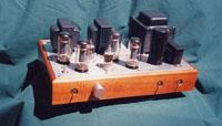 A picture of the layout. A picture of the layout.
There's a great deal of discussion and a strong awareness, in DIY audio, of the importance of implementation; as of course there would be. I saw a thread on a forum, where the subject was the relative 'percent importance' of circuit design (audio and / or power supply), parts selection, and implementation. You know, like, 25% design, 25% parts, and 50% implementation; the general run of the discussion being the high importance of implementation. Now, my own instincts on this run 100% design, 100% parts, 100% build, if you dig my jive; but any time I come upon a discussion about the overriding importance of implementation, my attention is complete, because two things are happening here for sure. First, these are guys who have built a lot of gear, and know what's happening. Second, there are going to be some juicy trix to be picked up; especially if they get a little irritated with each other and start bandying licks. My main instructor in the ECET program described an expert as, "Someone who's screwed up every possible way."
I've built a fair amount of gear myself now, and have screwed up a great number of the possible ways, I can tell you. I did some things building this amp that were very effective; and some things I wouldn't do again, and wouldn't advise you to do, either. It was an experiment in a number of directions; and where it turned out not to be an optimum piece (or at least an optimum prototype), it was at least a successful experiment - it gave a definite result.
One thing that's difficult to express about this amp in an image is its size: it's tiny! Look at the picture; those are 6V6's, and the 5965 is quite a small duotriode. Look at the size of the bias adjust pot shafts. The outside size of the chassis is 13" x 8½", the amp stands 6" tall on big rubber feet. This was an excercise in making a tube amp that wasn't big and impressive and room dominating, as a possible commercial product that would appeal to normal musical people, not audiogeeks like us. The inside size of that Koa wood chassis is 11½" x 7" x 2". There are four Jensen coupling caps in there, about the size of a 'C' battery, negative and bias transformers, and the rest of the regular catastrophe. It's tight. As a final commercial product it's okay, saved by the low filament and HV draw of its circuits; it pulls a steady-state 75 watts from the wall, signal or no, and doesn't generate much heat. As a prototype, a developmental mule, which is what us guys need, it's impossible. The amp sounds so good, I'd like to put a 100K DACT in it, replacing the RatShack pot; but where? I'd like to try loading the cathodes of the driver diff-amps (or the plates, or both) with the cool Hammond 150H choke; but where? Everybody on the Bottlehead List raves about the sonics of Doc's BJT constant current source (C4S) as a driver plate load; but effing where?
Unless you're pretty experienced at putting this stuff together, can get a soldering iron down past wires and stuff to the lug in question, and (like me) are fascinated with making it little and cute, and know for sure (unlike me) that this is the final version of the thing; I would definitely advise making it at least 15" wide, maybe even a standard 17". It's the depth, from front to back, that defines the length of the signal path; which must come from the RCA's in back, up to the switch and pot, then through the circuit back to the speaker posts, above the RCA's. At 15" wide, you'll have a half inch extra for each channel circuit, a half inch extra between the channels and between the audio section and the PS, and another half inch for the supply. Fat city, and no lengthening of the signal path. Make the chassis an extra half inch high, and you've got room to hang a signal choke from the top plate, or build a C4S on a terminal strip. The extra width allows you to build the channels straight, rather than angled like I did; with the 5965's in front (right behind the pot), and the 6V6 pairs side by side right behind them; and then you've got room for nice output transformers a little bigger than the peanuts from the Harmon Kardon receiver I used, without lengthening the signal path.
Before this amp, I had built them in the classic topography: tubes in front, iron behind, power supply in the middle, channels on the sides. It looks nice. All the shiny glowy bits are in the front, mostly hiding all the hulking industrial bits in the back. It hums. The power transformer and supply are right in the middle of all the audio circuitry; and unless you switch the main power on the back wall of the chassis, unacceptable for a commercial piece and pretty uncivilized anyway, your 120Vac has to run up to the power switches right by one of the channels. Because I was trying to minimize the size and implementation headaches of this amp, I decided to try a sort of pseudo two-chassis layout, with the audio circuitry on one side of the chassis, and all the line AC over on the other. The line cord entry and fuseholder are on the extreme right of the chassis rear panel. The white (neutral) wire goes to one primary pole of each transformer. The black (hot) wire goes to the fuse, and from there up the extreme right wall of the chassis to the power switches, and then to the other transformer primary poles. All the rectification is mounted as close to (mostly on) the right chassis wall as possible. The raw DC then moves leftward, toward the audio circuits, as it is filtered and smoothed, and thus orthogonally to the 120Vac, which is running mostly fore and aft in this part of the chassis. The only AC that gets anywhere near the audio circuit is the 6.3V for the tube heaters. These wires I install first (working from the bottom of the chassis), twisting them fairly tightly, and laying them right against the top chassis plate ground plane. The DC supply and signal runs are then installed where space permits, keeping them 'up' from the middle space of the chassis to the bottom plate. I try to keep the DC away from the signal as much as possible, and where it's neccessary to cross them, to have a little space between them and cross as orthogonally as possible. From this you may have gathered that I do not bundle and lace my wiring. It's the awful truth, and I live in fear of showing my web buddies a hood-up photo of my gear, because (at least in a photo) it's ugly. I have no faintest idea how those old guys kept the hum, interference, and channel crosstalk down in their gear, even with shielded signal runs. The developmental time must have been awesome. I've also done a bit of teching on old gear, and tracing a wire that disappears into a bundle is a pain. Automatic the thing is going to reappear in some inconspicuous place it'll take half an hour to find. Bundle and lace your wiring for the photo session, then get it back out there where you can trace and work on it.
The best-sounding amp I made with the classic layout was PP EL34's for my pal Richard Tadaki, and I chased hum and interference around that amp for over a month; finally ended up running all the AC in the thing through grounded copper water pipe. This amp has no shielding at all (except for the long signal runs), and from minute one, hum+noise has hovered around a millivolt on the output. This seems to be dominated by unequal heater-cathode coupling in the 6V6's. As they get old, around ten to twenty thousand hours, this increases, and they start to sound a little dull on top. When it gets up to 2mV or so, I replace them. I'm keeping them, though, because what I've heard from Bill Perkins and the guys on the Joelist is that they're probably becoming magnetized from the DC, which is causing both problems, and that degaussing (with a bulk tape eraser, maybe) will rejuvenate them. If this works, I'll test and resort them into quads and use my outputs forever.
If you go and look at any of the kit-based DIY audio forums, like the Bottlehead List, you won't have to go more than three posts down or so to see one like, "HELP, MY FOREPLAY (Paramour, Parabee, whatever) HUMS!" (Jeez, I just punched to verify the link, and the first hum post is miles down the list. Will I ever learn about shooting off my mouth? Have a look anyway, it's a good forum.) Anyway, it's certainly true that most of the problems we have with our circuits once we learn to assemble them correctly and get them operating electrically, are problems with hum and noise; which boil down to being grounding problems . So, what's a ground, anyway, and what's the problem? Let me explain this graphically.
 This is the basic DC circuit; you'll see it in any text. It's a closed loop (circuit, dig?), consisting of a power source (voltage, here); and a load, represented as a pure resistance. Current everywhere the same, volts over ohms; and net voltage drop if you go all the way around the circuit is zero volts. In practice, the source will be some sort of power supply, the load will be some useful circuit, but you can always reduce it down to this. You will notice that there is no ground in this diagram. This is the basic DC circuit; you'll see it in any text. It's a closed loop (circuit, dig?), consisting of a power source (voltage, here); and a load, represented as a pure resistance. Current everywhere the same, volts over ohms; and net voltage drop if you go all the way around the circuit is zero volts. In practice, the source will be some sort of power supply, the load will be some useful circuit, but you can always reduce it down to this. You will notice that there is no ground in this diagram.
The thing is; if you're going to tie this circuit (say it's a power output stage) into a system of similar circuits (say, a driver circuit, a biasing circuit, so on), there's no way to reference its net voltage to anything else. It's floating. Could be anywhere; all we know about it is that the top of the circuit is VT volts higher than the bottom.
 The solution to this is to make our circuits single ended. Since we usually power our circuits variable amounts (voltages, generally) from the positive side, we use a convenient common reference for the negative side; we stick 'em all in the damn dirt. We actually, do; and of course that's the origin of both the symbol and the name. In this way we can be assured of the way that different circuits will interact. The solution to this is to make our circuits single ended. Since we usually power our circuits variable amounts (voltages, generally) from the positive side, we use a convenient common reference for the negative side; we stick 'em all in the damn dirt. We actually, do; and of course that's the origin of both the symbol and the name. In this way we can be assured of the way that different circuits will interact.
Now, this setup is not without its problems, and the first of them is that the earth is not a perfect conductor. Being curious and having never done this, I just went outside and performed the experiment. Nice, damp, poststorm Hawai'ian dirt seems to have a resistance of about 10 kilohms per inch; higher than I would have thought, and hardly a big time ground bus.
 For this reason, we usually configure our circuits more like this. The ground is used primarily as a reference; no mega current is sourced or sunk here. If we tried to use it as an actual part of the circuit, its relatively high resistance would cause voltages to be developed in this component (volts equals amps times ohms, after all), very much affecting general operation of the circuit. For this reason, we usually configure our circuits more like this. The ground is used primarily as a reference; no mega current is sourced or sunk here. If we tried to use it as an actual part of the circuit, its relatively high resistance would cause voltages to be developed in this component (volts equals amps times ohms, after all), very much affecting general operation of the circuit.
This brings us to the second definition of the term ground, which is the zero voltage reference point. In a schematic, all points on a common line (representing a conductor) are considered to be connected to the same point in the circuit. Here, anywhere between the '-' of the voltage supply and the bottom of the load resistor is circuit ground. The thing to remember here is that, although the entire part of the circuit below (voltage negative of) the two main components is considered to be at zero volts reference, the entire current of the circuit is flowing through this conductor. Our zero-volts-everywhere assumption thus relies on a dependent assumption that the resistance in the total length of this conductor is exactly zero.
The predicament inside our gear is very much a microcosm of this situation. Audio components are DC circuits which are modulated, intentionally or otherwise, by AC. This amp has four power supplies and their load circuits attached to an ultimately common ground. Look at the power supply schematic. These are circuits that accept an AC voltage from the transformer, rectify it into very lumpy DC with diodes, and iron it out into (hopefully) nice clean, smooth DC for the load circuits. How? By using bigass expensive capacitors to shunt all the lumps to the ground reference. This is, in fact, the major AC signal that is being put on the ground bus, and the reason that most grounding problems manifest themselves in the form of 60Hz or 120Hz hum. At the same time, the PS 'hot' terminals are supplying about 150mA of current, in the form of that nice clean DC, to the audio and control circuit 'hot' terminals; all of which is doing its useful work in those circuits by losing its voltage potential, and being carried back to the bottom of the PS circuits (as in 'closed loop', right?). How? Via the ground reference.
 Now let's look at an audio amplifier circuit; we could replace 'RL' in any of the diagrams above with this. This is a plate loaded (or common-cathode) amplifier, the most common kind, and the type I use in this amp. This circuit doesn't look quite the same as those in the schems, but I'll get to that in the section on the design of the circuits . Also, I've omitted all DC biasing resistors and stuff, for clarity. The common description of this amp is that it amplifies (and inverts) the signal supplied to its grid, which is then taken off the plate. It is the cathode which is common (closed loop, again) to both signals; thus its two names. Look more closely, and you'll see that what the device actually amplifies is the voltage difference between its grid and its cathode - which is held at the ground reference. A signal supplied to either of these terminals will be amplified just the same; in fact, the first stage of the 6V6 amp does both these things. Now let's look at an audio amplifier circuit; we could replace 'RL' in any of the diagrams above with this. This is a plate loaded (or common-cathode) amplifier, the most common kind, and the type I use in this amp. This circuit doesn't look quite the same as those in the schems, but I'll get to that in the section on the design of the circuits . Also, I've omitted all DC biasing resistors and stuff, for clarity. The common description of this amp is that it amplifies (and inverts) the signal supplied to its grid, which is then taken off the plate. It is the cathode which is common (closed loop, again) to both signals; thus its two names. Look more closely, and you'll see that what the device actually amplifies is the voltage difference between its grid and its cathode - which is held at the ground reference. A signal supplied to either of these terminals will be amplified just the same; in fact, the first stage of the 6V6 amp does both these things.
Two things are probably occurring to you right about now. First, that the proper functioning of all this single-ended system depends very heavily on the net resistance of the ground reference being precisely zero ohms (so that no voltages are developed in this leg of the circuit); and that this is maybe not precisely the case. The second is that, the preceding being true, this grounding deal is starting to look like a real can of worms. Right on, bro or sis; that queasy feeling you're having about the grounding of your piece is bringing you onto common ground with people who have many years of schooling in this discipline. There's also a kicker here; in that it's important, both for operator safety and to inhibit the ingress of RF nasties into the circuit, to have the box that it's mounted in grounded as well; this now becoming also a part of the ground reference.
There are a few well known and respected strategies and tactics (military logic: strategy is what you plan to do to deal with what you expect the enemy to do; tactics is what you actually do to deal with what the enemy is actually doing) for keeping your gear quiet in the face of this can of worms. Since they both make sense and have worked for me, I shall elaborate. The first is to make sure that the ground leg of the circuit has as low a resistance as possible, from end to end. The obvious way to do this, of course, is to make the ground leg of the circuit as short and fat as possible. The extreme execution of this is called star grounding. Rather than using a ground wire or bus to collect the negative ends of all the assorted circuits and supplies, they are all brought to a single point. I use a disc about the size of a quarter made from copper flashing material, with enough holes drilled in it to accept all the circuits, plus one, and mount this to the first power supply capacitor (the 100µF one) ground terminal. A good operative version is to use a piece of the copper about 3/4" wide, that goes from the first to second PS caps, and to drill the holes in between. All the ground legs of the audio circuits and their power supplies are brought to this point, which is then taken to chassis ground at some point selected experimentally, usually near the inputs / outputs. This is electrically a very effective method of holding the entire ground reference (and attached chassis) at a very close approximation of zero volts. All residual wire resistance is then attached to the individual circuits, and is of negligible effect there. The only problem with this method is that it's an implementation headache; in pieces with some physical size, and multiple circuits, the ground wires are numerous and long, and really clog up the chassis. What I ended up doing was bundling them together to minimize their obstructive physical presence, which led me to an inevitable conclusion.
The ground bus technique is a very close electrical approximation of star grounding that avoids the million miles of ground wires everywhere. The ground reference is a nice fat (I use 12 gauge Romex conductor) wire that runs the length or width of the chassis, to which individual circuit and PS grounds can be brought at convenient points. This is then brought to chassis ground as before; usually starting at this point. I start mine at the rear chassis wall, attaching it to the bus that picks up all the ground sides of the input RCA's. The output transformer secondary grounds and the (also fat) wire to the chassis, which is attached to an output tranny mount, attach right here also. The bus runs straight forward through the chassis, ending up at a terminal strip that's mounted to a front screw of one of the input tubes; about an inch from the front wall of the chassis. All the power supply grounds are gathered at the ground terminal of the dual 100µF PS cap, and then brought to the bus by a piece of 16 gauge stranded (a cutoff of the line cord). I tried positioning this major pickup experimentally, and could not measure or discern any difference at any reasonable position. Try it yourself. The ground bus should not be brought to chassis at more than that one point. This creates a circuit (loop, remember) called a ground loop, which can develop considerably more current (and noise) than the single-ground bus. That is, the bus (between the two chassis ground points) forms one leg of the circuit, and the chassis (between the two bus ground points) the other. A great deal of the troubleshooting in pro-sound and recording studio situations involves finding and eliminating ground loops.
When I make little compact circuits, I star ground. For larger circuits like this amp, I use a ground bus. Careful design and neat construction make the difference in either case. For instance, there's a fair amount of 60Hz 'pulse' current in the bus; and though very little voltage will be developed in the low-impedence ground circuit, this signal can be inductively coupled to any DC or signal conductor running parallel and close to it, and can develop effective voltage in those high-impedence circuits. Experiment. After a couple hum removal episodes, you'll start to develop an instinct for it.
You have probably noticed that there is very little in the way of dimensioned drawings, specific cut-it-this-size-and-drill-the-hole-here instruction giving on this page. There are some sound reasons for this. First, this is a versatile and economical little amp. I've thought of building it into a console-type radio, the ultimate boombox, and a few other configurations where I think it would work very nicely. You may well have your own ideas about the physical form you would like it to take. There's also the question of the applicability of any detailed instructions I might give you. My methods are based on my skills and tools, and yours on yours. I've spent the last, God, fifty years building motorcycles, guitars, hang gliders, sailboats, muzzle-loading rifles, and this stuff. Often, when I give my amateur craftsman friends specific directions in answer to their questions, they just stare at me for a minute, and then cuss me out. If my detailed instructions on making all the double-sided mortises in the chassis in the picture would mean anything to you, you probably wouldn't need them anyway. What I've tried to do is give a good fundamental exposition of how I think an amp ought to be implemented; counting on your own good common sense and my e-addy at the bottom of each page to bridge the gap. An interesting thing: I've talked with several people who are/were building this amp, and none of them built exactly what's on the page. I welcome your questions, comments, and ideas as well.
Okay, I do have one very specific instruction for building this, or any other amp, or DIY thing: with a few details.
Take Responsibility For Your Own Welfare
There seems to be an amazing attitude among Americans for the past few years that somehow they are entitled to have their personal safety provided for them from outside by somebody. Life is not safe. You get into DIY audio, through this page or anywhere else, you're going to be engaging intimately with high voltage electronics, power tools, toxic substances, immoral hippies like me, sex (hopefully), drugs (maybe), rock'n'roll, and other physical and spiritual hazards of modern life. Get a grip. One thing I can tell you for sure about being down here on the planet is that no one gets out alive; but you can statistically lengthen your stay here in the Rec Audio suburb of the Vale of Tears by observing a few general and specific fundamental rules. Herewith:
Be Careful You will observe that I did not say, 'be fearful,' or, 'be tentative,' the adjectives that many people would associate with the term 'careful'. Fear is not care. Care involves understanding of the potential hazards of an action, and address of those hazards with appropriate precautions, executed with firm and decisive action.
I do most of my millwork on the table saw, a very dangerous implement; and I read a terrific article in a woodworking magazine yonks ago about advanced techniques on this tool, that taught me a lot. One of the repeated exortations in this article when making a dangerous cut was, 'be confident.' You can't be tentative with a three horspower motor driving an eight inch razor less than an inch from your fingers. If your amp is powered up upside down on the bench, and there are various hundreds of volts in various places in there, and you need to stick your hot probe on them to verify the correct number of hundreds, and you don't know exactly where they are, then don't be tentative; shut the booger down and go back to the documentation, review the situation until you're sure what's happening, and proceed - confidently.
Observe the Standard Precautions They are the fruit of screwing up every possible way. I shall recite as completely as I can:
- Build the circuit in small subcircuits, and test each one individually; even if it's just visual inspection of the solder joints and verification that all the connections are correct. Build the front end (driver) section of the audio circuit of each channel, and check it. You can't check electrically until everything's complete, but go back and check that you have all the tube socket pins identified and wired correctly. The tube socket terminals are the closest uninsulated points in the circuit, and there's nothing you can do about that; make sure that you don't have an uninsulated wire end or component lead lying across anything it shouldn't. Inspect each solder joint visually and wiggle it gently while you look. If you're not nearsighted as a mole, like me, go down to the drug store and get a pair of those reading glasses in the strongest power they have, like +3. Now, do the same thing with the output circuit. Don't be lazy; go back and check every damn thing. Wire up the heater supply, and check that it develops the correct voltage, this will be 6.3Vac. Put the tubes in their sockets and verify that they're lighting up. Then build the bias supply and verify that it develops about negative 36Vdc at the tops of the pots; and adjust the pots to give about negative 22-23Vdc at the 6V6 grids. Then build the negative supply and verify that it develops about negative 170Vdc into an open circuit (tubes not plugged in). You will note that we've built and checked electrically every circuit that we could, and especially checked the output control (bias) circuit for correct operation, and set it a little on the conservative side.
-
Now build the positive supply, and inspect visually. In many cases, including this one, if you've built using the specified values, you will not be able to power up this supply without a load, as it will develop voltages in excess of the ratings of the main reservoir caps (the 100µF 350V caps are going to be very unhappy with 425 volts across them - perhaps fatally so), so this is the point at which you will have to plug in all your tubes and test the whole circuit for voltages, as described in the section above.
Some people spring the seventy bucks for a variac (variable output line transformer) so they can bring everything they test up to voltage slowly, and test at low voltage (say, 25-30v into the cord) for correct operation without all the adventure: this seems like a good idea to me, I'll probably get one my next order from one of the general vendors. If nothing else, it will save a lot of time, as I find myself checking everything four or five times sometimes before fireup, in anxiety. It's making me sweaty just writing this.
Turn on the heaters, and let everything warm up a minute. Put your probe on the output of the HV main supply (the positive terminal of the first 100µF filter cap is the handiest place, probably), look at the circuit closely, and turn on the HV main. This voltage should take about 5 seconds to rise up to 300-315Vdc. If anything happens besides what you have studied and can reasonably expect to happen, turn off the HV main switch right now and find out why. If it doesn't, walk through all the voltage points, and record the readings, starting with the output bias test point (adjust the bias at this time, using the pot, until the test point reads 1 volt exactly) . A really common sign that all is not well is noticeably loud transformer buzzing when you flip the hot switch. This usually signals a short somewhere. If it's a big bad short, you'll just see a quick blue flash as the fuse goes. Thank you fuse. Until everything is going cooly, don't take your thumb off that switch.
-
Test everything you can on a dry circuit. I've been doing this a fairly long time now; and I still don't much like sticking a conductive probe tip down in a nest of assorted high voltages to find the one I want. All continuities and resistances can (in fact must) be checked on a cold circuit, and these will almost always tell you if the circuit is assembled properly. The voltage checks on the live circuit are for verification and adjustment. If you've had the circuit running, unplug it; or the line ac will still be live in there, and put your probe on the main PS caps to verify that they are at zero or negligible volts. If not, put a resistor, say, 100K 2W, across the terminals to drain down. Some folks will put a 220K 2W permanently across here for this purpose, called a drain-down. My amp doesn't have one; there probably wasn't room.
-
When testing on a live circuit, keep one hand in your pocket. This is an old, funny sounding, and no kidding rule. If you're holding on to the ground plane with one hand and put the other on HV main, you're sending that zap right across your heart and lungs; and the next person you talk to might very well be St. Peter. Clip lead your negative probe to the ground reference, and, no fooling, stick your off hand in your pocket. I'm so damn dumb I have to hook my thumb in the back of my belt; hand in my pocket doesn't feel weird enough, and I'll forget.
This is the same reason to wear shoes if you're working on a grounded (bare concrete or tile) floor; that zap goes right down through your thorax on the way home. Not being well grounded, especially through the thorax and brain, really does minimize the effect of a 400 volt zap. Maybe you'll be carefull enough not to ever get one. I've gotten a few; the last one I woke up sitting on the floor (couldn't have been long; I was sitting). That was the last one; I mean it. Really.
-
Be effing careful! Doesn't matter if it's a live circuit, a running power tool, a fast motorcycle, or a fast woman. Have your procedure set; know what you're doing, and why; know what you're going to do if it goes wrong. Keep your eyes and ears open, and your brain in gear. Never mind about the fast woman; I know nothing about fast women.
IF YOU'D LIKE TO PULL A PRINT,
HERES A PRINT-FRIENDLY VERSION OF THIS PAGE
|
