|
I've been promising Epstein to make this thing for a year now. I have all the parts for it, including the quartet of 6C45 's I got from him. The thing is, it will produce about 3 watts of power, max; and I just don't have any speakers for an amp this size. So, what has happened is that this project has led to this other project about some 94dB or hotter speakers. The proposal for that project is up here too, and I'm cutting dirty old AC plywood for the test boxes right now, the version for Diatone P610MB's. If it wasn't a rainy day, that's what I'd be doing instead of sitting here making this page, in frustration. As soon as I have that optimized a bit, I'll be starting on this amp; and this time I'm not going to build the cabinet-grade version right off. I'll breadboard it up on a piece of plywood, like you're supposed to; so I can smash and crash at will. 's I got from him. The thing is, it will produce about 3 watts of power, max; and I just don't have any speakers for an amp this size. So, what has happened is that this project has led to this other project about some 94dB or hotter speakers. The proposal for that project is up here too, and I'm cutting dirty old AC plywood for the test boxes right now, the version for Diatone P610MB's. If it wasn't a rainy day, that's what I'd be doing instead of sitting here making this page, in frustration. As soon as I have that optimized a bit, I'll be starting on this amp; and this time I'm not going to build the cabinet-grade version right off. I'll breadboard it up on a piece of plywood, like you're supposed to; so I can smash and crash at will.
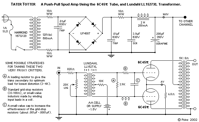
This will be, by far, the most experimental circuit I've designed so far. Its operation revolves around two very remarkable components; and will use another unusual application as well. A glance at the schematic will show that it's the ultimate expression of the all-differential, simpler-is-better approach I've been exploring since I started doing this stuff. Since most line-level components produce a single-ended signal, this signal is split by an input transformer immediately after volume is set; thus, the entire amplifier circuit can operate in fully-balanced differential mode. 'The entire amplifier circuit', in this case, consisting of exactly one differential pair of devices, loaded by an output transformer. Now, all you guys who've designed and built a few pieces are looking at this circuit and saying, "Wo, this looks ver-ry marginal to me; that input tranformer and those tubes better really be doing a job, or output is gonna be right up there in the milliwatt range."
When Per first pointed me at the LL1527XL, and I went and looked at the specs, I wondered if there was some mistake. The bandwidth is so wide, the distortion so low, it's like the magical forked piece of wire that will split the signal and otherwise disappear. Maybe. It 'likes' a pretty specific input and output impedence to look at, and making the input preference (800 ) with a volume control requires a shunt arrangement with a resistance low enough to worry me, as far as drive from the average CD player or tuner is concerned. At low volumes, the source component is going to be looking into an impedence of a couple kilohms or less, and must be able to drive this load without rolloff at either frequency extreme. I show a couple of different grid circuits here, and a shunt-type volume control; both are pretty provisional. The plan is to fart arou - ah, experiment with arrangements here, while listening and looking at the waveform on the scope; and try to get it to wor - ah, optimize the performance of the circuit. I'm sure I can find a 'sweet spot' where it'll work like crazy; but the question, in my mind, is if it can be made to work over a wide enough range of volumes (source impedences) to be viable. Of course, by 'work', I mean work trancendentally; fabulously. I have the trannies, gorgeous little cubes of mu-metal, and they weren't cheap, so I hope so. ) with a volume control requires a shunt arrangement with a resistance low enough to worry me, as far as drive from the average CD player or tuner is concerned. At low volumes, the source component is going to be looking into an impedence of a couple kilohms or less, and must be able to drive this load without rolloff at either frequency extreme. I show a couple of different grid circuits here, and a shunt-type volume control; both are pretty provisional. The plan is to fart arou - ah, experiment with arrangements here, while listening and looking at the waveform on the scope; and try to get it to wor - ah, optimize the performance of the circuit. I'm sure I can find a 'sweet spot' where it'll work like crazy; but the question, in my mind, is if it can be made to work over a wide enough range of volumes (source impedences) to be viable. Of course, by 'work', I mean work trancendentally; fabulously. I have the trannies, gorgeous little cubes of mu-metal, and they weren't cheap, so I hope so.
I don't know who first noticed the 6C45 . It's evidently a Soviet military type; someone said it's a component from MiG radar. It, also, has an absolutely amazing set of specs. In the example circuit: . It's evidently a Soviet military type; someone said it's a component from MiG radar. It, also, has an absolutely amazing set of specs. In the example circuit:
Plate current . . . . . . . . . . . 40 mA
Plate Voltage . . . . . . . . . . 150 volts
Transconductance . . . . . . . 45 mA/V
Plate Resistance . . . . . . . . 1155
Mu Factor . . . . . . . . . . . . 52
Max Plate Dissipation . . . . 7.8 watts
I found a set of plate curves at www.tubes.ru, and redrew them for readability. Here's the graph.
If you look, you'll see that the device operates at 40mA quiescent current, and transconductance is 45mA/V; this thing will fully modulate with a line level input signal! A plate resistance of about 1200 puts it in the mainstream of output tubes, so output transformers with the correct load (4 - 6K puts it in the mainstream of output tubes, so output transformers with the correct load (4 - 6K ) are going to be available; and a plate dissipation limit of about 8 watts means that we can get about 4 watts output out of a push-pull pair of them, if they're optimally loaded. ) are going to be available; and a plate dissipation limit of about 8 watts means that we can get about 4 watts output out of a push-pull pair of them, if they're optimally loaded.
This device has characteristics somewhat similar to the (legendary) Western Electric 437A, leading some experimenters to try it in 'Potato Amp' or 'Spud Amp' ('one tuber', groan) circuits for which the 437 was known, which has revealed another virtue. As phenomenal as the specs seem, they are quite conservative. Some guys (Steve Bench? Bob Danieliak?) have reported use at OP's approaching 200 volts and 50mA, the entire internal structure glowing; and happily making beautiful music. The two pairs of them I got from Jeremy list tested specs on the boxes of 46 and 47 mA/V.
Now, the sort of sensitivity performance that these two components display is not without its problems. Anything that gets into the circuit, signal-wise, is going to stay there, and get amplified. A lot. The self-resonance point of the LL1527 is simply listed as being 'greater than 200KHz', which will be pretty safe in most audio circuits, but this is a tiny and efficient trans, and that resonance is probably pretty pronounced. Meanwhile, the 6C45 made its military living in the microwave range, up in the gigahertz; so it will have no problem amplifying that resonance, should it come along. This is a potentially very jumpy circuit, that might regard anything from stray radio or cellphone waves to nasty thoughts on the part of the builder as signal. Everyone who's used this device shows ferrite beads on the heater leads, good-sized caps everywhere on all non-signal DC and AC supplies, grid-stop resistors, and every other anti-oscillation trick you ever saw. The problems, in short, do seem to occur. made its military living in the microwave range, up in the gigahertz; so it will have no problem amplifying that resonance, should it come along. This is a potentially very jumpy circuit, that might regard anything from stray radio or cellphone waves to nasty thoughts on the part of the builder as signal. Everyone who's used this device shows ferrite beads on the heater leads, good-sized caps everywhere on all non-signal DC and AC supplies, grid-stop resistors, and every other anti-oscillation trick you ever saw. The problems, in short, do seem to occur.
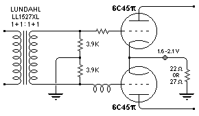
 For this reason, as I said, the design shown here should be regarded, except for its basic topology, as entirely provisional. At right are shown alternate grid circuit and (self) biasing schemes for the amp. These do not neccessarily go together. That is, the self (cathode resistor) output biasing could be used with the center-tap grid circut; the fixed bias could be used with the split-resistor grid circuit; mix and /or match. Alternatives abound. One of the big advantages of the very simple circuits we use in vacuum tube ultra-fi has always been the viability of element-by-element tuning of the individual circuit for most soulful performance; and this amp will undoubtedly require such massage.
As an experiment, this project is meaningful to me. It's the natural extension of what I've been doing in rec audio since I started. It also looks like it just might be a really killer 3 - 4 watt amp; it bears the same relationship to single-ended 2A3's that my present amp (the PP 6V6's) does to single-ended 300B's. As soon as I have speakers for it to play into, I'm going to build up; and I'll report my experiences, I promise; so check back. If you get there before I do, I'd appreciate it if you'd report in, too. I'm at poinxie@yahoo.com, and I welcome questions and comments.
Poinz
IF YOU'D LIKE TO PULL A PRINT,
HERES A PRINT-FRIENDLY VERSION OF THIS PAGE
|
