|
I've been doing some studying of the currently favored horns, and TQWT,s and such; and come to a suspicion that there's a
problem that afflicts most folded horns and tubes; that they're really nowhere near their theoretical optimum shape, but a very loose polygonal approximation. I feel it very worthwhile, if we're going to construct horn and pipe loads for drivers, to trouble ourselves to make them smooth, nicely folded (if they're folded), and if they're horns, dimensionally rigorous. The problem with the advanced
loadings is that it seems like everybody's trying to see how poorly they can be constructed and still work. Why? Might as well make a well-designed VB and get it over with.
One of the things that attracts me about the Diatone (in addition to its rep for natural sound) is that its
TS params seem to make it suitable for an untapered TL, which is a much easier load to construct optimally than a folded horn; which is a very difficult load to design and construct accurately. Both the lines drawn here are long enough not to need stuffing unto death, nice and smooth in their contours, and have a novel feature in the horn mouth, which I hope will help their room coupling, and thus bass production.
The process / technique that makes these nice curved lines possible is called kerf bending. A kerf is the slot left by a saw blade; for a power circular saw, this is typically 1/16" to 1/8". Kerf-bending is a way to make relatively thick pieces of wood take fairly tight bends, or radii.
 Let's take a piece of, say, 3/4" plywood, say, 7 3/4" wide; taken from the long dimension of the panel, grain of the outside ply on the long run. If we make saw cuts across the piece, almost all the way through, at regular intervals of about 1/2" to 1", we can bend the piece in a pretty tight curve.
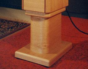
If you go look at the stand under the speaker in the picture, you'll see that we can make quite a tight bend this way. I've; a bit of skill in this technique, having made some few constructions in this way in my other life as a cabinet maker. If we make the kerfs (kerves?) on the inside of the piece (that is, the piece is bent so that the kerves/kerfs close and touch), and make them at regular intervals; the piece will take an even radius, determined by the spacing of the, ah, saw cuts. The 'trick' to doing this efficiently is to design the construction to use as few radii as neccessary (which the boxes above do), and use scrap stock to determine the spacing of the kerves that will produce these radii. There is a problem with the places where the curves feather into each other and into the straight pieces, as the little slots are only glued together at their tips (the inside surface), and the piece will come apart catastrophically in the saw when cut on the long angle. How do I know this; hm-m? In those sections, I fill the slot with a little triangular piece of wood; as wide as the slot at its base, and as long as the slot is deep. 3 or 4 slots at the feathered end of each of these pieces will need this treatment. The 'profile' of the line is built up on one of the side panels (which has the profile drawn on it), using clamps and spreader sticks and tape and whatever sneaky tricks will get the job done; then the wires and any stuffing or damping is put in; then the remaining side is put on. These are long and smooth enough that they may not require stuffing except right behind the driver, to curb reflections back through the cone; so I'll just line the area around the driver and down the curve with half inch felt, set the wiring, and close 'em up.
Let's take a piece of, say, 3/4" plywood, say, 7 3/4" wide; taken from the long dimension of the panel, grain of the outside ply on the long run. If we make saw cuts across the piece, almost all the way through, at regular intervals of about 1/2" to 1", we can bend the piece in a pretty tight curve.
If you go look at the stand under the speaker in the picture, you'll see that we can make quite a tight bend this way. I've; a bit of skill in this technique, having made some few constructions in this way in my other life as a cabinet maker. If we make the kerfs (kerves?) on the inside of the piece (that is, the piece is bent so that the kerves/kerfs close and touch), and make them at regular intervals; the piece will take an even radius, determined by the spacing of the, ah, saw cuts. The 'trick' to doing this efficiently is to design the construction to use as few radii as neccessary (which the boxes above do), and use scrap stock to determine the spacing of the kerves that will produce these radii. There is a problem with the places where the curves feather into each other and into the straight pieces, as the little slots are only glued together at their tips (the inside surface), and the piece will come apart catastrophically in the saw when cut on the long angle. How do I know this; hm-m? In those sections, I fill the slot with a little triangular piece of wood; as wide as the slot at its base, and as long as the slot is deep. 3 or 4 slots at the feathered end of each of these pieces will need this treatment. The 'profile' of the line is built up on one of the side panels (which has the profile drawn on it), using clamps and spreader sticks and tape and whatever sneaky tricks will get the job done; then the wires and any stuffing or damping is put in; then the remaining side is put on. These are long and smooth enough that they may not require stuffing except right behind the driver, to curb reflections back through the cone; so I'll just line the area around the driver and down the curve with half inch felt, set the wiring, and close 'em up.
As soon as it stops raining, I'm going to be on these things like a dog on a bone; so check back in a while, and see what happens. They just might work, you know.
|

